
The daily maintenance of key components of float glass melting furnaces is fundamental to prolonging the furnaces' service life, extending the service cycle of the entire production line, and enhancing economic benefits. Taking the common problems of the regenerator in float glass furnaces as the discussion object, the causes, influences, and common treatment methods of the regenerator blockage were mainly discussed. Meanwhile, some effective daily control and preventive treatment methods have also been proposed, providing useful references for prolonging the service life of furnaces.
On both sides of the glass melting furnace, there are several vertically symmetrical and independently separated regenerators. During the production process, they not only play a role in heat exchange between the combustion-supporting air and the exhaust gas but also serve as channels for the combustion-supporting air to enter the melting furnace and participate in the operation of the combustion system. They also act as channels for the exhaust gas of the melting furnace and participate in the waste discharge work of the melting furnace. They are vital to the stability of the process inside the furnace. It is vividly compared to the "lungs" of a furnace. Therefore, if the regenerator is not used and maintained scientifically and reasonably during the production process, it will affect the normal operation of the melting furnace, lead to a reduction in production capacity, and in severe cases, directly impact the service life of the melting furnace.

1. The reasons for the blockage of the regenerator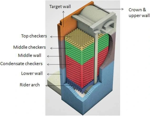
2. The impact caused by the blockage of the regenerator
3. Daily maintenance of the regenerator
4. Daily protection of the regenerator
1.The reasons for the blockage of the regenerator
The blockage of the regenerator in glass furnaces is a key issue affecting the thermal efficiency and stable operation of the furnaces. Its causes are complex and mostly result from the interaction of physics, chemistry and process operations.
From a physical perspective, the ash produced by fuel combustion (such as silicon-aluminum oxide particles) and the unmelted fine powder in the glass compound (such as soda ash, silica sand, etc.) enter the regenerator with the high-temperature gas flow and gradually deposit in the pores of the lattice body, forming a dense accumulation layer. Meanwhile, foreign objects such as debris produced by thermal shock or mechanical stress of refractory materials and metal tools accidentally dropped in during maintenance can also directly block the channels.
The chemical blockage is even more concealed and highly harmful. During the glass melting process, the vapors of alkali metal oxides such as sodium and potassium that volatilize condense in the low-temperature zone of the regenerator and react with the alumina and silica in the refractory blocks to form low-melting-point cabernet minerals (such as NaAlSiO₄). These substances solidify in the form of a glass phase after cooling, resulting in a sharp decrease in porosity. And with the expansion of volume, the lattice structure is further squeezed. In addition, elements such as sulfur and chlorine in the fuel generate sulfates (Na₂SO₄) or chlorides (NaCl) after combustion. These not only directly corrode refractory materials but also solidify into viscous deposits in the low-temperature zone, exacerbating the narrowing of channels.
Improper operation and management should not be ignored either. For instance, frequent temperature fluctuations caused by a too-short fire change cycle will accelerate the cracking of refractory blocks, while if the temperature at the bottom of the regenerator is controlled too low (such as below 800℃), it will prompt the premature condensation of alkali vapor. An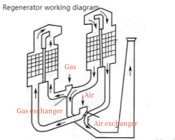 abnormal gas flow rate (either too high or too low) can disrupt the balance between dust carrying and deposition, creating local "dead corners" for dust accumulation. Design flaws and incorrect material selection can also pose hidden dangers. For instance, insufficient porosity of the lattice body (< 40%), poor alkali corrosion resistance of refractory bricks (such as ordinary high alumina bricks used in high-temperature areas), or insufficient thermal shock stability (such as magnesia bricks) can all shorten the clogging cycle. From the perspective of the clogging locations of the regenerative chamber grid bodies, the areas with more severe clogging of individual regenerator grid bodies are mostly located at the edges of the regenerative chambers. The main reason is that the temperature distribution difference leads to lower temperatures at the edges, which intensifies the condensation of sulfuric acid and alkali metal oxides, resulting in clogging.
2.The impact caused by the blockage of the regenerator
The blockage of the regenerator will have a significant negative impact on the operational efficiency, energy consumption, product quality, and equipment service life of the glass furnace. The specific manifestations are as follows:
(1) The thermal efficiency has declined and energy consumption has increased significantly
Heat exchange obstruction: Blockage leads to a reduction in the heat exchange area between flue gas and air, preventing the regenerator from effectively recovering waste heat and increasing fuel consumption (typically with energy consumption rising by 10% to 20%).
Abnormal fire change cycle: Frequent fire changes are required to maintain temperature, further intensifying energy waste.
The flue gas temperature rises: The flue gas cannot fully release heat, the flue gas temperature rises (up to over 500℃), and the heat energy loss intensifies.
(2) The operational stability of the furnace has deteriorated
Intense temperature fluctuations: The blockage of the regenerator leads to an unstable preheating temperature of the air, and the temperature of the furnace flame fluctuates greatly (above ±50℃), affecting the homogenization of the glass liquid.
Uneven air distribution: Local blockage causes deformation of the air flow channel, forming "short circuits" or "dead corners", which aggravates local overheating or overcooling.
Incomplete combustion: Insufficient preheating of air leads to a decline in fuel combustion efficiency, generating unburned gases such as CO, which pollutes the environment.
(3) The quality of glass products has declined
Melting defects: Temperature fluctuations cause uneven viscosity of the glass liquid, which is prone to defects such as bubbles, streaks, or stones.
Uneven composition: Disorder of the heat system in the melting furnace may affect the decomposition of compound materials and the homogenization of glass liquid, leading to fluctuations in chemical composition.
Difficulty in forming: The decline in temperature control accuracy directly affects the drawing forming process, resulting in uneven thickness or broken plates.
.png)
(4) Shortened service life of the equipment
Thermal stress concentration: The temperature gradient in the local blocked area increases, and the risk of thermal shock spalling of refractory bricks rises.
Deformation of supporting structure: Long-term blockage may cause uneven force distribution on the walls or supporting beams of the regenerator, leading to structural deformation.
(5) Maintenance costs have soared
Increased frequency of ash cleaning: Frequent shutdowns are required for manual ash cleaning or high-pressure water gun flushing, which increases labor and time costs.
Rising maintenance costs: When severely clogged, checker bricks need to be replaced or partially dismantled and rebuilt. The cost of replacing refractory materials is high (accounting for 30% to 50% of the total maintenance cost).
Production halt losses: Unplanned shutdowns for maintenance lead to a decline in output, affecting the company's profits.
(6) Environmental protection and safety hazards
Excessive emissions: Incomplete combustion leads to an increase in the emissions of pollutants such as CO, NOx, and SO2, resulting in environmental protection penalties.
Fire risk: When the accumulated ash contains unburned carbon particles, it may spontaneously combust and cause a fire at high temperatures.
Structural collapse risk: Severe blockage may cause a local overheating or load-bearing imbalance in the regenerator, posing a risk of collapse.
(7) Limited production flexibility
Difficulty in load regulation: After the blockage, the furnace is hard to respond quickly to the demand for output adjustment, which affects the delivery of orders.
Limited process optimization: It is impossible to optimize the melting process by adjusting the heat change cycle or temperature curve.
3.Daily maintenance of the regenerator
By observing the reflection of the bottom grid holes in the regenerator, the temperature changes of the branch flue, and other means such as taking photos with an endoscope, the blockage condition of the grid body can be detected in a timely manner. In the early stage, some measures can be taken, such as blowing away the accumulated ash in the furnace bar arch through the blowing hole, adjusting and opening the branch flue gate plate to increase the flue gas passing through the grate body and raise the temperature of the grate body. Measures such as appropriately reducing the air volume blocking the port, minimizing the heat loss of the grate body, and ensuring the temperature of the grate body are taken to maintain the basic stability of the grate body temperature. However, the above methods can only alleviate the clogging condition of the grid body to a certain extent, cannot completely solve the problem, and some measures will affect the process inside the furnace. Therefore, when it is found that the grid body is severely clogged, it should be treated in a timely manner. Common governance methods include:
3.1 Mechanical unblocking method
The mechanical unblocking method refers to the method of unblocking by poking the grid holes from the bottom, that is, using a poking rod for manual unblocking. Generally, from the bottom of the furnace bar arch on the burning side (and sometimes from the non-burning side), a connecting rod is used to break the blockage in the grid holes by impact and push it open, causing it to fall. Due to the high height of the grid body, it is usually necessary to make longer push rods or multi-section detachable connecting push rods according to the size of the grid holes. The top section has a pointed head and wings on the side of the rod. Due to the relatively high temperature in the construction area, construction is mostly carried out on the upwind side. The fire is changed every 20 minutes, and the effective construction time is approximately 15 to 18 minutes. Due to the large number of grid holes, the progress of the mechanical unblocking method is relatively slow. When mechanically unblocking, the corresponding flue gate plate is usually lowered or locked first to reduce the passage of hot air flow. At the same time, the ash cleaning door of the regenerator is in an open or semi-open state to allow air to enter and cool down the operation site. However, the entry of cold air will cause problems such as a decrease in the furnace temperature and an 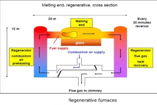 increase in furnace pressure. Moreover, as the bottom ash cleaning door needs to be opened multiple times for personnel to enter and exit, it has a relatively significant impact on the stability of the furnace process. At present, with the maturation of grid body dredging technology and the update of protective equipment, various companies have begun to choose non-fire side dredging. The unblocking on this side has a relatively small impact on the process, but the working environment temperature of the personnel will rise, the personnel replacement time will be shortened, and the unblocking efficiency will further decrease. In addition, the space at the bottom of the grid body is limited, and the grid holes near the wall of the regenerator at the edge are usually severely clogged, making the unblocking difficult and the unblocking progress slow. Therefore, more often than not, the unblocking of the middle part is the main focus to improve the unblocking efficiency. When there are too many blockages in the grid holes, the operation is rather difficult and sometimes they cannot be cleared. Therefore, when mechanical unclogging is adopted, the unclogging rate is usually slightly lower. Especially when large-scale sulfuric acid alkali metal oxide coking and blockage occur, mechanical unblocking methods are difficult to carry out.
3.2 Bottom firing method
The bottom-burning method refers to the use of a special fire gun to heat the grid holes from the bottom of the regenerator's grid body upwards, causing the blockages accumulated in the grid holes to melt and flow down. At present, natural gas is mostly used, while liquefied petroleum gas and diesel are also employed. The load-softening point temperature of the furnace grate body bricks is generally above 1400 ℃, while the melting temperature of sulfate-type blockages is usually around 900 to 1100 ℃. Therefore, controlling the flame temperature of the combustion gun at 900 to 1200 ℃ can effectively melt the blockages and prevent damage to the grate bricks at the same time. In the actual processing, it is usually necessary to assess the condition of the checker bricks and the furnace bar arches. Because during the bottom firing process, the blockage and the checker bricks may undergo local co-melting, the control of flame temperature and direction during heating is extremely important. Generally, experienced professional companies are chosen for the construction. In addition, if the blockage is a fallen or cracked checker brick, the heating method is ineffective in clearing it, and it will further increase the risk of collapse.
3.3 Heat exchange of checker bricks
During the loading and unloading of the firing gun and the cleaning of waste residue, the bottom ash cleaning door of the grid body needs to be opened for personnel to enter and exit, which has a certain impact on the furnace process in a short period. This heating process is a continuous operation that requires personnel to take turns on duty. Operation observation holes will 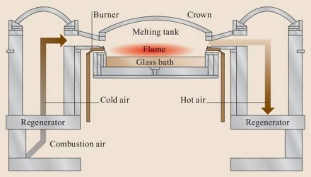 be reserved to facilitate the observation of the operation situation and the adjustment of the angle and position of the firing gun. The operators can operate outside the heat storage room, and the working environment is relatively good. Only during the ash cleaning process do personnel need to enter the heat storage room for construction. This method has a relatively fast operation progress and a good unblocking effect. It is mainly used for severely clogged grid bodies. Generally, the unblocking rate through the heating unblocking method can reach over 80%. The waste gas produced during the heating and unblocking process and the gas components generated by the heating of sulfates have a significant impact on environmental protection data. Therefore, before the operation, it is necessary to pay attention to the local environmental protection policies and report to the environmental protection department in advance. During the operation, the flue gas desulfurization and denitrification process should be tracked in real-time. Some enterprises, after going into production, do not attach importance to the protection of the regenerator, resulting in severe blockage and damage to the checker bricks, which cannot be dealt with by mechanical unblocking or bottom firing. At this time, the checker bricks need to be replaced. The heat exchange of checker bricks is a method of replacing one or more checker bricks in the regenerator through a hot state without halting production. It is generally used in the later stage of furnaces where the checker bricks in the regenerative chamber are severely blocked or collapsed, seriously affecting production, etc. The current heat exchange technology for checker bricks is relatively mature, with controllable safety risks. The regenerator after heat exchange has the same functions as the new furnace regenerator. However, the costs of purchasing bricks, consumables, and construction for heat exchange are relatively high. The construction process has a certain impact on production, and at the same time, the construction process has high requirements for process control.
The following points should be noted:
(1) Due to the reduction in the number of regenerators involved in combustion during the heat exchange of the grid body, and the large-scale opening of the hot repair door to draw in cold air for cooling, maintaining the temperature inside the furnace is of Paramount importance. According to the temperature requirements, appropriately reducing the drawing volume and adding crushed glass can make up for the heat gap caused thereby, reducing production losses, and increasing the speed of process recovery after hot repair.
(2) During the heat exchange process, to prevent the temperature in the heat exchange area from dropping too rapidly, a portion of the natural gas in the port in the construction area also needs to be retained for combustion. However, since the original combustion-supporting air channel has been blocked, the required combustion-supporting air is met by measures such as increasing the air ratio of the adjacent port and controlling the leakage of some cold air into the heat repair insulation board. Therefore, the insulation board on the water bar should not be sealed too tightly to ensure that the combustion of this port is normal. The flame doesn't turn black. When performing operations such as opening or closing the hot repair door and the ash removal door, laying or removing the insulation board, etc., it is also a point where the amount of cold air leakage undergoes sudden changes. At this time, the furnace pressure and flame combustion conditions will change significantly. It is necessary to adjust the heat load and air ratio in a timely and sufficient manner according to the actual situation to ensure normal furnace pressure and flame.
(3) The number of layers of the replaced checker bricks should be consistent with the original design to keep the heat storage capacity of the replaced regenerative chamber the same as that of other regenerators to the greatest extent, so as to ensure that the preheating temperature of the combustion-supporting air remains unchanged and improve the combustion efficiency.
4.Daily protection of the regenerator
The problem with the regenerator is not caused by a temporary unreasonable process. It usually goes through a relatively long process. Therefore, it is very necessary to establish a set of scientific, reasonable, and complete measures for the use and maintenance of the regenerator system.
(1) Regularly conduct reflection checks on the grid bodies to accurately monitor and assess the changes in grid body blockage. The reflection changes at the bottom of the regenerative chamber grid bodies are the most direct indicator of the blockage condition of the grid bodies.
(2) Pay attention to the temperature changes.At the top of the regenerator and the branch flue, set up warning temperature values. When the temperature reaches or approaches this value, process adjustments should be made to prevent accidents in the regenerator. The change in the temperature of the branch flue, to a certain extent, reflects the smoothness of the grid body and has a certain precursive nature. When a certain grid is clogged, the flue gas volume flowing through that grid will decrease, thereby reducing the temperature of that grid. At the same time, it will also cause the flue gas volume of adjacent grids to increase and the temperature to rise. The decrease in temperature will make the volatile substances in the flue gas more likely to condense, further aggravating the clogging situation. Excessively high temperatures can lead to intensified ablation of the lattice body, posing a threat to safety.
(3) Opening degree of each port gate plate. There is still some debate regarding the opening degree of each port gate plate at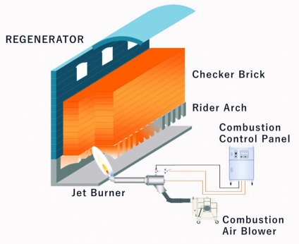 present. It is generally believed that the fundamental function of the exhaust side gate plate is only to extract exhaust gas. According to this view, the opening degree of each port gate plate should be determined based on the amount of exhaust gas produced at the corresponding part of the melting furnace.
(4) The atmosphere in the melting furnace affects the clarification and bubble removal capacity of the glass liquid. Therefore, during the process of unblocking the grid body, it is necessary to constantly monitor the combustion condition of the spray gun and the residual oxygen situation in each regenerator to ensure the stability of the atmosphere in the melting furnace.
(5) Make a long-term maintenance plan for the grid body. Based on the daily inspection results of the melting furnace, regularly clear the blocked grid holes.Clean the furnace ash under the furnace bars in the regenerative chamber.
(6) When formulating the temperature curve of the melting furnace, the protection of the regenerator should be taken into account. Situations such as overly long flames and excessively high temperatures should be avoided to prevent direct damage to the regenerator.
The occurrence of problems in the regenerator usually requires a relatively long process. The blockage of the grid body may be caused by the collapse of the grid bricks, or it may be due to various reasons such as sulfate condensation or dust accumulation. The fundamental reason for the deformation and collapse of brick materials is that the heating temperature of the brick materials exceeds their load-softening point. The rational use and maintenance of the regenerator system is one of the important tasks for enterprises after they go into production. When the grid body is clogged, reasonable treatment should be carried out to ensure the normal and stable production process as much as possible. At the same time, it is very necessary to formulate a reasonable and complete set of measures for the use and maintenance of the regenerator system, which can, to a certain extent, effectively prevent and slow down the blockage of the grid body.
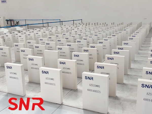
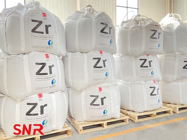
In the long-term operation practice of the regenerator system, the scientific selection of materials directly affects the maintenance cost and production stability. Based on the current widespread problems of grid blockage and brick failure, it is recommended to give priority to the use of SNR series high-performance refractory blocks.
Henan SNR Refractory Co., Ltd (SNR) understands that each furnace has unique working conditions. If you need further information on product parameters, please feel free to contact me.
Web:www.snrefractory.com
Email:moon@snrefractory.com
