
Glass furnaces are core equipment in glass production, whose operational stability and service life depend on the proper selection and construction quality of refractory materials. The construction process of refractories not only affects the thermal efficiency and energy consumption of the furnace but is also critical to ensuring the purity of molten glass and production safety. This article systematically outlines the construction procedures and technical essentials for refractory materials in various parts of glass furnaces, aiming to provide standardized references for engineering practices while emphasizing the profound impact of high-quality refractories on overall furnace performance.
Flues
When laying the top layer of bricks in the flue bottom, align them perpendicular to the airflow direction. Start construction from the center of the flue and proceed toward both ends. During flue construction, reserve expansion gaps of approximately 10mm every 3m straight length, staggered vertically and horizontally. The masonry around the air exchangers should be installed after the damper frame is inspected and approved.

Regenerators
1. The outer walls of regenerators must be staggered and interlocked, avoiding vertical seams between adjacent rows of clay bricks (insulation bricks) and red bricks. Stagger every 4–5 rows.
2. The separation wall of the regenerator shall be made of staggered joints. The expansion joints shall be left at the positions of the regenerator door stacks at both ends of the dividing wall. Clay mud is used for clay bricks and silicon mud is used for silicon bricks. Mixing is strictly prohibited.
3. Regenerator grate bars must not tilt, and their spacing must be strictly controlled. The leveling surface of grate bars must be precisely aligned.
4. For burner and regenerator door arches, install the arch formwork and verify alignment before construction. Secure the arch foot bricks and semi-circular arch bricks before building the door arch. Lock bricks for door arches should protrude 30mm above the arch crown and be grouted after installation.
5. The actual centerline deviation of burner and regenerator masonry should not exceed 5mm.
6. Before laying a semicircular arch, it is necessary to test the semicircular arch horizontally and vertically to check whether it is qualified and to determine the size of the mud joints.
.png)
7. The weighing horizontal arch of the port should be built in a circle, and its locking bricks should be 50mm higher than the arch top. They should be hammered in together with a wooden hammer, and then grouting should be carried out. The port can be built after the bracing bars of the heat storage chamber columns are tightened and the arch bricks leave the arch tire.
8. The stacking of lattice bricks must be vertical and horizontal, the error of the center line of each lattice hole should not exceed 5mm, the error of the lattice hole size should not exceed 6mm, and the horizontal error of the upper surface of the lattice brick should not exceed 8mm.
9. The holes for blowing in the regenerator sealing wall must be left facing each longitudinal lattice hole and sealed with a Saitou brick.
When laying the regenerator wall, clay bricks must be laid between the grate arch foot, the semicircular arch, and the outer wall reinforcement iron parts.
Port
1. The centerlines of burner uptakes must align with design benchmarks, with a deviation ≤5mm. Paired burner centerlines must coincide within 10mm, and burner axes must remain perpendicular to the furnace chamber centerline.
2. Ensure accurate cross-sectional dimensions and neat burner corners for seamless steel structure installation.
3. Reserve a 30mm expansion gap between the burner throat bottom and front wall, temporarily filled with straw rope during construction.
4. Burner arches are constructed using mortar-brushed bonding.
5. Secure both sides of burner arch lock bricks with angle steel supports.
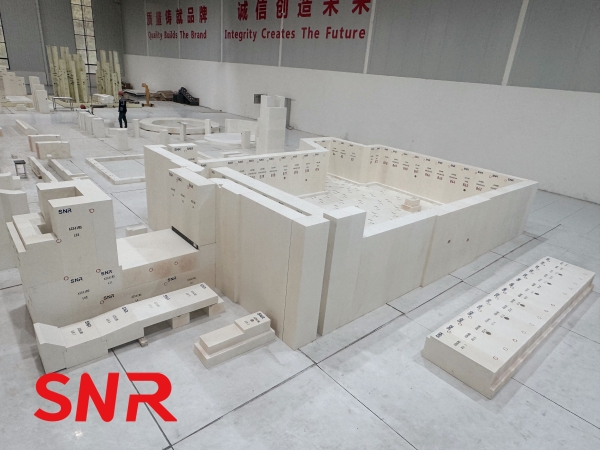
Furnace Bottom
1.Large clay bricks for the furnace bottom must be dry-stacked after selection, machining, and numbering. Discard bricks with cracks, voids, or edge damage exceeding 30mm (outer) or 10mm (inner).
2.The large clay bricks at the bottom of the furnace should be processed on all surfaces except the surface in contact with the molten glass. The processed surface of the bricks should be checked with a ruler and a square. The gap between the ruler and the brick surface should not exceed 1mm.
3.Lay bottom bricks from the centerline outward. Align brick joints perpendicular to bottom steel plates, maintain parallel rows, and insert 50mm-thick paperboard into expansion gaps to prevent debris ingress.
4.Level the furnace bottom, especially near sidewall areas, to ensure overall horizontal accuracy.
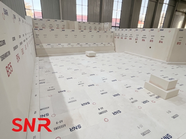
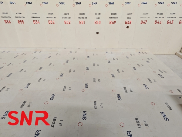
Sidewalls
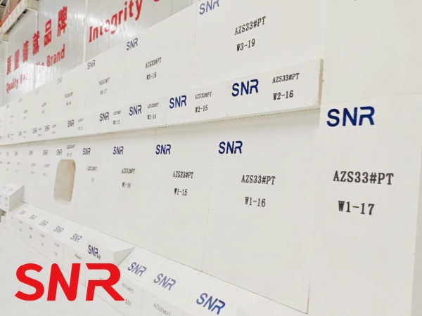
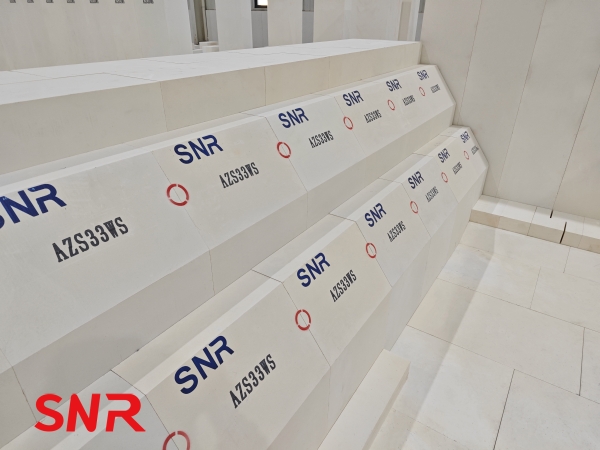
1.Weigh fused cast sidewall blocks individually, prioritizing denser bricks for high-temperature zones like the melting zone, doghouse, and throat entrance.
2.Construct sidewall corners with straight seams, avoiding staggered bonding. Ensure vertical alignment with longer wall sections.
3.Sidewalls must be straight, with cast ports of mullite or zirconia-corundum bricks facing inward. Vertical joints must be staggered, with gaps ≤5mm.
4.The elevation tolerance for sidewall tops is ±10mm, with the melting zone height not lower than the throat front wall.
5.After the sidewall, bottom and superstructure that come into contact with the glass liquid are all built, the inner surface of the masonry should be cleaned of dirt with a steel brush and blown clean with compressed air.
.jpg)
Breast wall
1. When laying tuck stones and breast walls, measures should be taken to prevent them from tipping into the furnace. When placing tuck stones, pull a line on the cast iron plate to level and spread a thin layer of mud, tighten it with wooden wedges on the sidewall, and place the tuck stone head on the wooden wedges to keep the hook surface level and prevent it from tilting into the furnace due to unstable center of gravity when laying the breast wall.
2. When the tuck stones are dry-stacked, the upper surface should be leveled with a level ruler. Leave 1 to 1.5mm expansion joints between each hook turn, pad the joints with horse manure paper, and pull them out after laying. However, no expansion joints are left between the tuck stones facing the I-beam column, and a 5mm expansion joint should be left between the tuck stone surface of the tuck stone and the cast iron plate.
3. No expansion joints are left between the upper gap bricks and the large arch. Each brick is hammered solid. The back of the upper gap must be clamped tightly. The contact surface between the small surface and the large arch corner is required to be sealed with mud. The contact surface between the large surface and the large arch brick is required to leave a gap of 3~5mm.
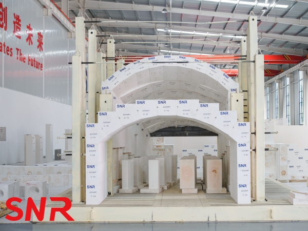
Crown
The masonry of the large arch is the most critical. The arch span of this melting furnace is 10800mm, and the masonry material of the large arch is 400mm thick silica bricks, weighing about 312.6t. This project adopts the insertion type small furnace mouth (a total of 8 pairs), so there is no counter-arch on the large arch.
Crown Construction Process:
Centerline marking → Pre-layout → Control line and expansion joint marking → Brick placement → Bricklaying → Lock brick installation → Grouting → Tensioning → Joint finishing.
(I) Pre-arrangement
After the installation of the arch tire is completed, carefully check and adjust the span, arch height, tread curvature, and arch top elevation. After they are all qualified, mark the longitudinal center line and the expansion joint line of each arch brick on the arch tire to pre-arrange the arch brick. During the pre-arrangement, pre-arrange one ring at each end of each arch, and determine the size of the mortar joint based on the actual size of the on-site pre-arrangement. Install a pre-made large-curvature keel frame at the end of the arch and the expansion joint. This frame should be 20-30mm higher than the arch brick so it is convenient to pull the wire.
(II) Laying out the wire
To ensure the overall beauty of the large arch surface and no misalignment, a parallel control line is laid out according to the thickness of the arch brick as the masonry reference line according to 3 rings. The position of the temperature measuring hole brick is laid out based on the center line of the 1# port. Control points are also popped out on the keels at both ends of each section. This point is the reference for pulling the wire on each ring of the arch brick surface. After the laying out work is completed, 1/5 of the bricks used for the entire arch are stacked on the arch formwork, and the arch formwork bearing capacity is observed. If there is no abnormality such as sinking, the masonry of the arch can be started.
(III) Masonry
The arch is generally divided into 5 to 7 sections, and the length of each section is between 5 and 8 meters. To ensure the overall quality of the column arch, the masonry should be completed in a relatively short time, and the bricks should be locked before the mortar dries. It is not suitable to have too many people to build the arch. Generally, 6 technicians are arranged for each section. During construction, the masonry should be symmetrical, and each row of arch bricks should be built from both ends to the middle at the same time, and the speed should be consistent. There are 3 technicians on each side of each section, and each ring is built longitudinally, and the upper line is drawn from both ends to the middle.
During masonry, the big and small heads of arch bricks are strictly prohibited from being placed upside down. Each brick should be mortared and laid. The mortar saturation of the flat joint and the top joint should reach more than 95%. Use a rubber hammer or a wooden hammer for correction. Use a card to check the angle of the arch brick after each ring is laid, and use a 4000mm aluminum ruler to check the flatness.
(IV) Tightening the tie rods
After the large arch is built, the tie rods should be tightened immediately. Before tightening the tie rods, the temporary fasteners on the steel parts and the wooden wedges on the breast walls on both sides should be removed. The purpose of tightening the tie rods is to make the brick body of the entire arch and the supporting steel structure become a whole. The amount of tightening data is determined by the size of the arch collapse, which is roughly controlled at about 1‰ of the arch span. Generally, the method of directly observing the changes in the arch crown is adopted to observe the amount of upward bulge of the arch crown after the horizontal tension of the tie rod to reflect the force of the arch crown.
(V) Removal of wooden formwork
Remove the wooden wedges under the column, let the entire wooden formwork fall about 100mm, check the overall condition of the large arch, and then use wooden strips to push up to let the plywood and strips on the arch piece detach from the arch piece, and then remove the wooden formwork, clean it up and transport it out. Check whether there are arch bricks with broken corners, cracks, inversions, etc. on the lower arc surface of the arch. If there are any quality conditions, they should be replaced in time, and then the joints should be pointed and cleaned. After inspection, the construction of the large arch has met the design requirements, and then a comprehensive cleaning is carried out, finally, the bottom bricks of the furnace are laid, and the exit is protected until the furnace is ignited.
Conclusion
The construction of refractory materials for glass melting furnaces is a highly specialized and sophisticated system engineering, which requires strict compliance with process specifications to ensure masonry accuracy and material adaptability. From the expansion joints of the flue, the staggered masonry of the heat storage chamber, to the straightness control of the sidewall, and the symmetrical brick locking process of the arch, the rigorous execution of each link directly affects the long-term stable operation of the melting furnace.
In this process, the quality of refractory materials is the basic guarantee. Taking the high-temperature and easily corroded parts such as the sidewall as an example, the high temperature resistance, corrosion resistance and structural density of the fused cast AZS blocks directly determine the service life of the melting furnace.Only through the combination of scientific construction and high-quality materials can the high efficiency, energy saving and long-term operation of the glass melting furnace be achieved.
Henan SNR Refractory Co., Ltd(SNR) produces a variety of high-quality fused cast AZS blocks.If you have any needs, please contact us.
Web:www.snrefractory.com
Email:moon@snrefractory.com
